At work, we’re using microcontrollers. We use them to monitor equipment and the environment, also to control machines in ways such as automating tasks and/or responding to certain environmental conditions. I work on the enablement team, therefore it’s part of my mission to facilitate other teams in their goal achievement. The automation team is responsible for planning and execution of automation projects. As an application developer, I’m acquainting myself with the tools and techniques of their team to help enable them on the software side of things. For one of my first tasks, I was given a GPS receiver and an Arduino Uno.
Getting Started
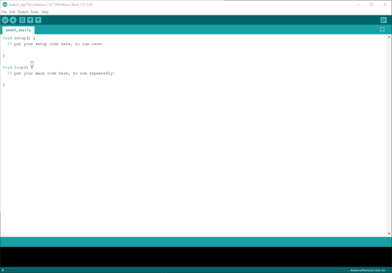
The first order of business was to figure out how work with the Arduino. I was using the Arduino Uno, which is a common microcontroller. The folks who make it also provide an IDE – Integrated Development Environment – for programming it. On a visit to their website, I downloaded the IDE and installed it onto my computer.
Connecting the Uno and the IDE
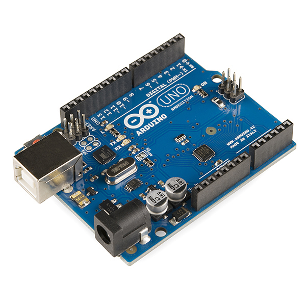
Connecting the Uno to the IDE was pretty straightforward. You can see in the picture of the Uno below that it has a USB type B port (like those commonly used on printers). The Uno connects to the computer using this USB port. Once connected, from the top menu of the IDE select Tools > Board > Arduino/Gunuino. This tells the IDE which board you’re using. Next, you need to inform the IDE which communications port the Uno is using. I was initially making the connection on a PC running Fedora Linux so I selected /dev/ttyACM0 from the menu under Tools > Port. I then received a permissions error, so I gave my user permissions to that device (/dev/ttyACM0). On Windows, it was a little easier, I simply selected selected COM3 and it just worked.
My First Sketch
In the parlance of the Arduino world, the code the controls the microcontroller is called a sketch. It’s as simple as drafting the code and hitting the upload button – the arrow under the top bar menu. Alternatively, you can select Sketch > Upload or press Ctrl+U to upload the sketch in the IDE to the microcontroller. Here’s a simple “Hello World” program:
void setup() {
  // put your setup code here, to run once:
  Serial.begin(9600);
  Serial.println("Hello World!");
}

void loop() {
  // put your main code here, to run repeatedly:

}
Output
Hello World!
The Serial.begin; part sets the baud rate – roughly the number of bits per second – that’s used for communication over the serial line, and Serial.println puts the characters ‘H’, then ‘e’, then ‘l’, then ‘l’, then ‘o’, and so fourth on the line and finishes with a new line character (\n) which causes the console to advance to the next line. There’s also a Serial.print which does not append the new line, and had I used it the console would not have advanced to the next line of output.
Connecting the GPS Module
I could now program the Uno, but without anything attached there’s not a whole lot one can control with the microcontroller. I needed to connect the GPS module to the Uno so I could start receiving data.
First Comes Power
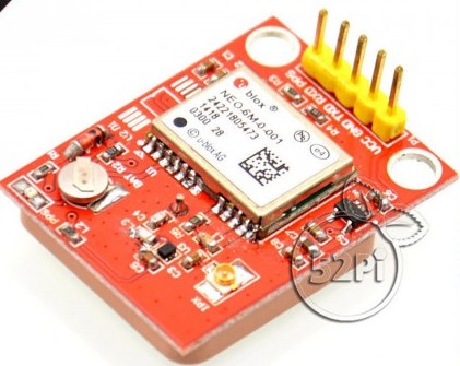
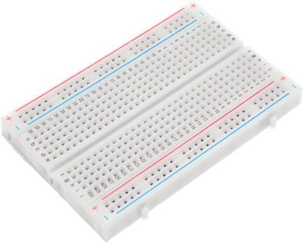
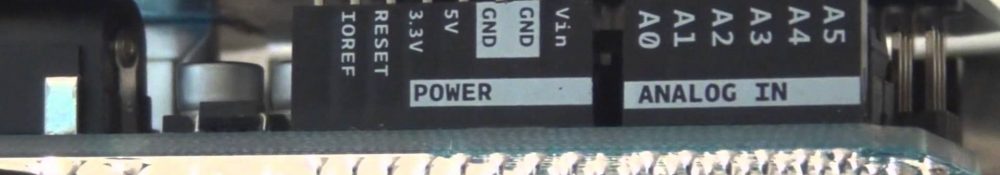
The module I was using was the Ublox NEO-6M, which operates using 3.3 volts supplied by the Arduino. I plugged the module into a breadboard (pictured below) and provided power by plugging one jumper wire into the Uno’s ground (GND) and another into the 3.3V power port. Then I plugged the other ends of those wires into the corresponding breadboard holes for the GPS module’s ground and voltage input (VCC).
Here’s a picture of the board assembled.
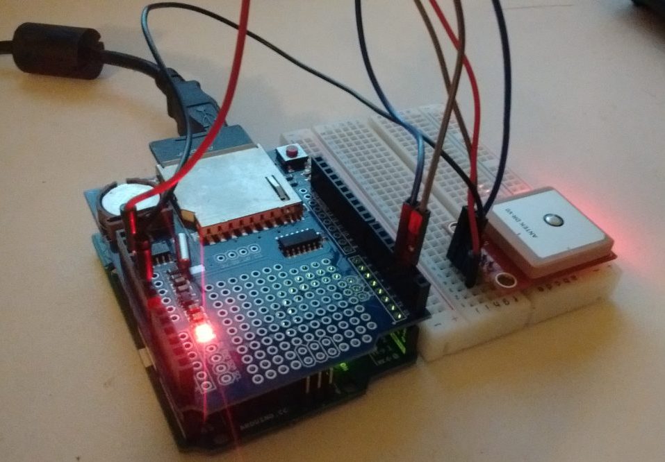
In the picture, you can see the GPS module plugged into the breadboard and the jumper wires connecting the power (red) and ground (black). You may also notice, there’s something on top of the Uno. That’s called a Shield, and we’ll get into that later. There are also 2 other wires – a gray and a blue on the opposite side as the power wires) which I haven’t yet mentioned. Those are for communication with the module. One is for transmitting data, and the other is for receiving.
Setting up Communication with the Module
To actually do this communication, we’ll need a software library named SoftwareSerial. To import a library into the development environment, from the IDE’s top menu bar select Sketch > Include Library > SoftwareSerial. You’ll notice an #include statement was added to the top of your sketch.
#include <SoftwareSerial.h>
The include statement is sort of like a shortcut code that says, “copy and paste the SoftwareSerial library here.” With that library of code available, we can now set up our Uno to “talk” to the GPS module. We’ll configure digital pins 2 and 3 respectively as receive and transmit. Add the following line to your sketch; below the include statements area at the very top.
#include <SoftwareSerial.h>

SoftwareSerial mySerial(3,4);

void setup()
{
  Serial.begin(9600);
  mySerial.begin(9600);

  Serial.println("Hello World!");
}

void loop()
{
  // put your main code here, to run repeatedly:
}
For some reason, unbeknownst to me, when initializing/constructing the SoftwareSerial object (the statement we just added), the pin number are offset by +1. On the Arduino, I have the jumpers plugged into ports 2 and 3, but I’m using (3,4) in the constructor function call. I’m guessing this is because the SoftwareSerial library is using pins indexed from 1, whereas on the Uno the pins are indexed from 0.
Now my Uno and GPS module are setup to talk to each other.
Adding GPS Module Libraries
To actually “talk” to the GPS module, I used another software library named TinyGPS. This wasn’t packaged with the IDE, so I downloaded the code repository and added to the IDE. To add a library, from the top menu bar select Sketch > Include Library > Add .ZIP Library and select the zipped code repository.
This will automatically add the #include <TinyGPS.h> line to the top of your sketch. Also in the code, you’ll find an example sketches that you can use to figure out how to get the GPS data from the module. I found an instructable with some sample code that made getting the GPS data pretty simple. You can try visiting the linked instructable and downloading the NEO-6MGPS.rar archive and running that code on the Uno. You should see similar output:
In a subsequent post, I’ll go over actually using the data.